Category: Project

Mini mobile phone tripod from the 3D printer

Today a little report about how I 3d printed a tripod for my mobile phone:

Mobile phone mount

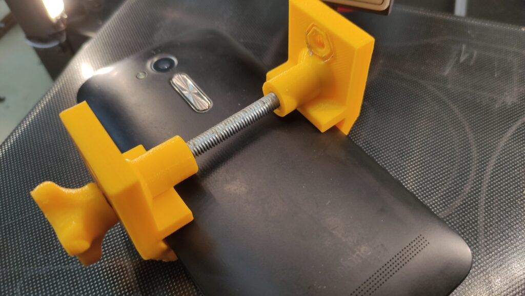
I chose the following model as my mobile phone mount: https://www.thingiverse.com/thing:366210. The parts were printed quickly and were quite stable:
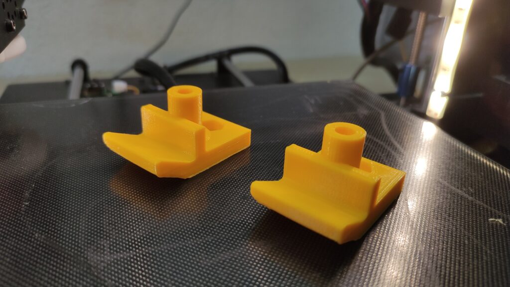
Handyklemme 3D Druck

Since I didn’t have a suitable nut, I printed it out. Of course, I could have used others, but I wanted to make the whole thing compatible with standard tripods.
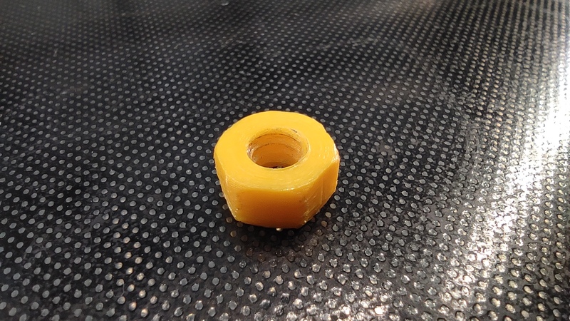
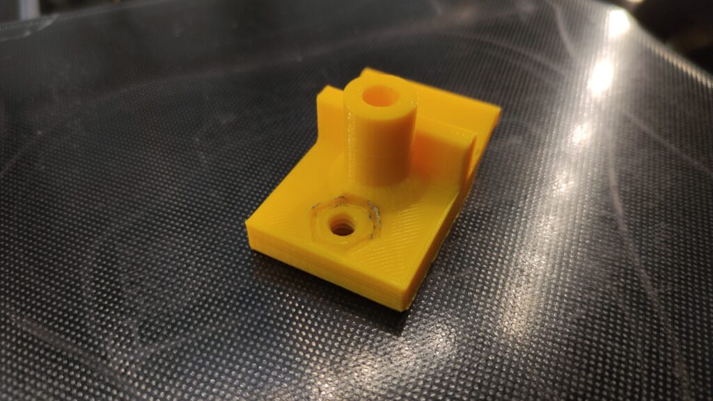
3D Druck Mutter
Handyklemme 3D Druck

At the end, a nice handle that I melted in the nut:
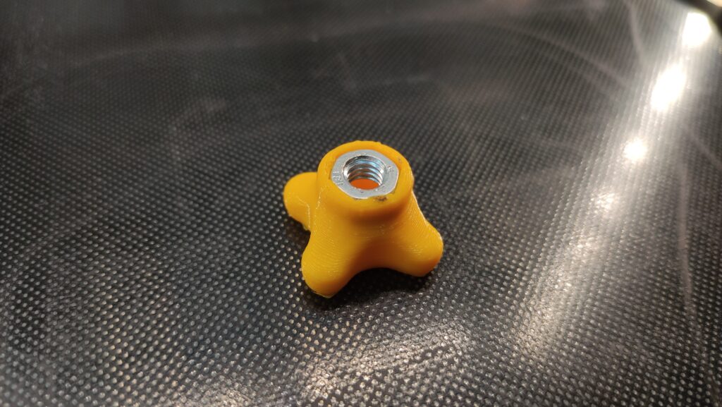
Mutter mir 3D Druck Griff

Now I put a screw or threaded rod through the phone mount and fixed it with hot glue:
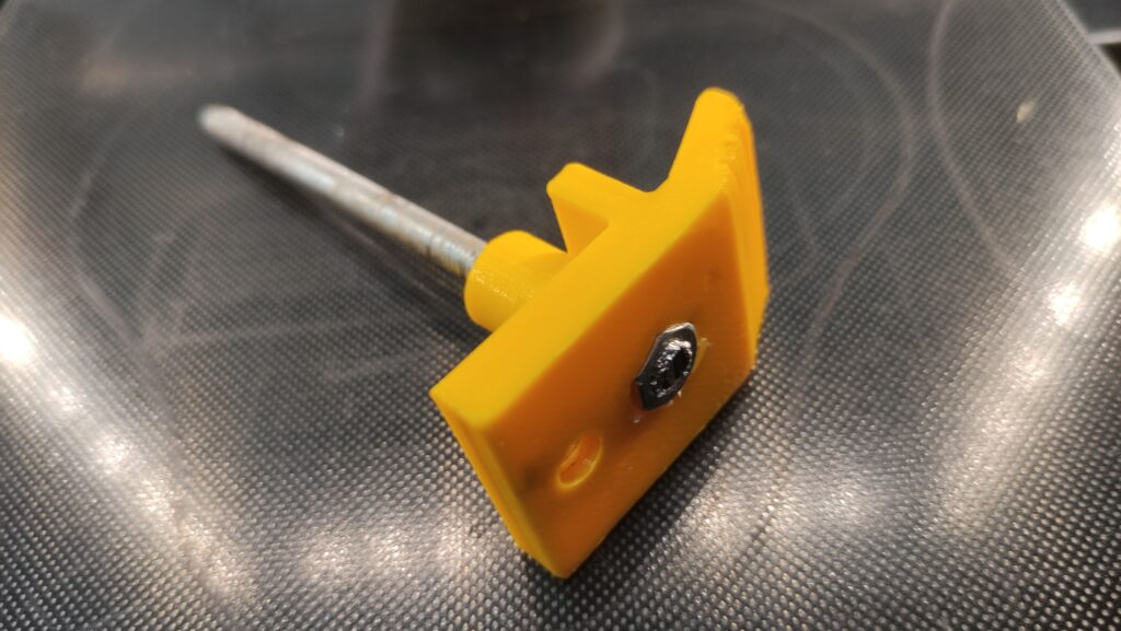
Handyklemme 3D Druck Zusammenbau

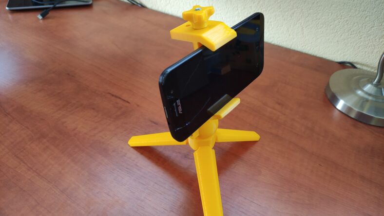
Assembled, the whole thing looks like this:
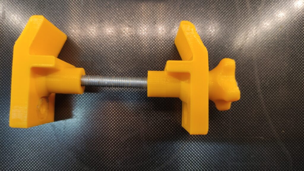
Handyklemme 3D Druck

So the mount itself would fit on a tripod. But since it was too big for my intended use, I printed out another mini tripod.
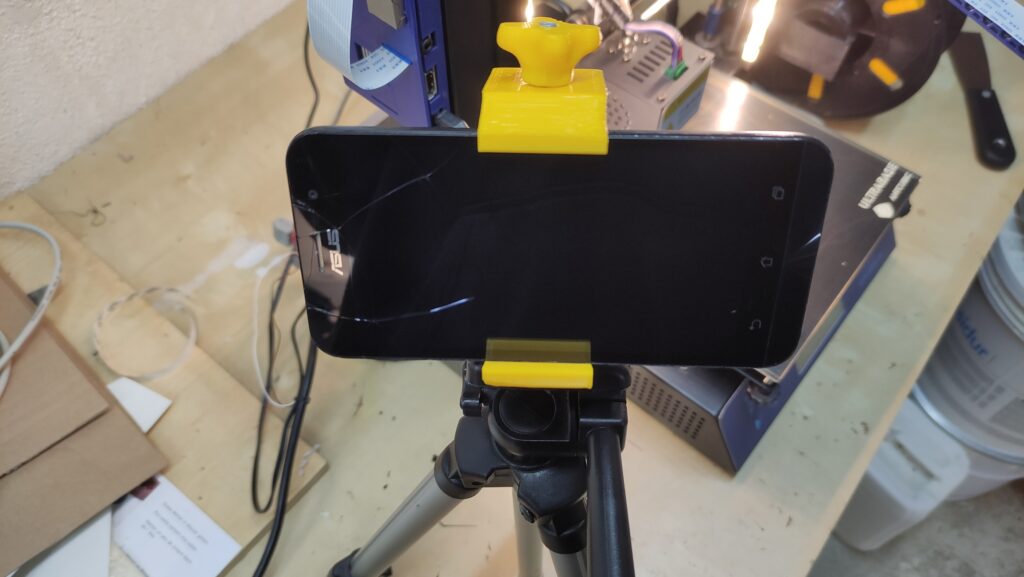
Handyklemme 3D Druck auf Stativ

Tripod

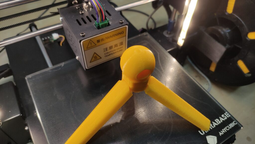
Here I have selected this tripod. The main part looks like this and is printed “print in place”:
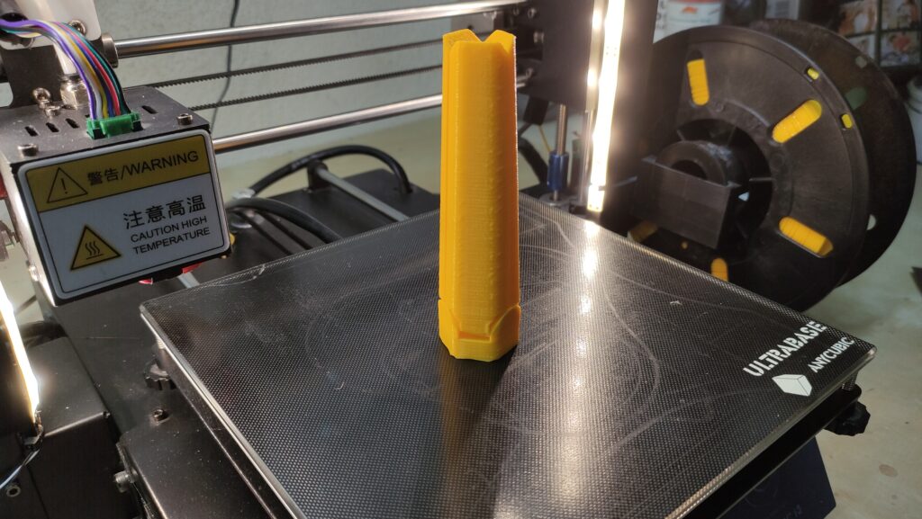
Stativ 3D Druck

With a little force, you can then unfold it:
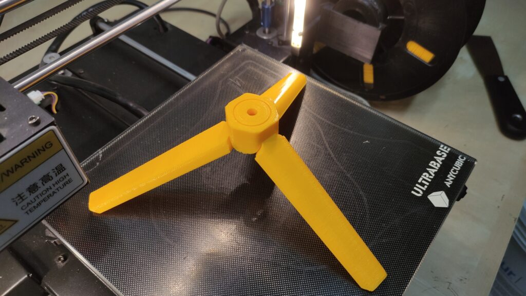
Stativ 3D Druck ausgeklappr

Since this design also works with the screws I don’t have, I printed out two more screws of this type and attached them in the stand with hot glue:
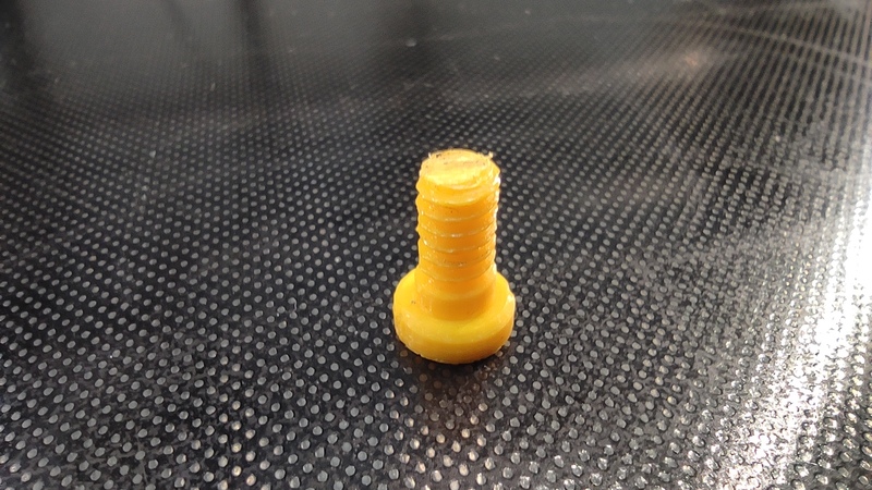
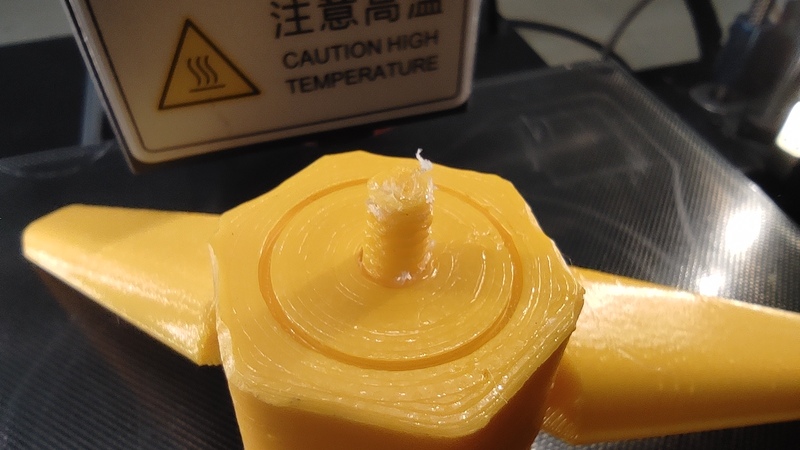
Schraube 3D Druck
Schraube in Stativ

You also need such a screw for the part that encloses the ball:
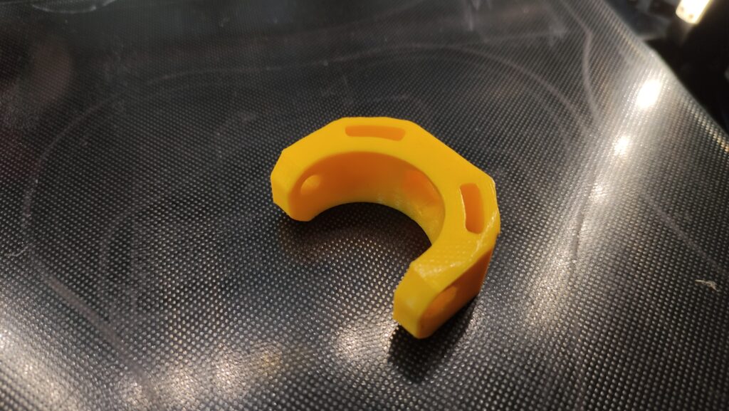
Teile für 3D Druck Stativ

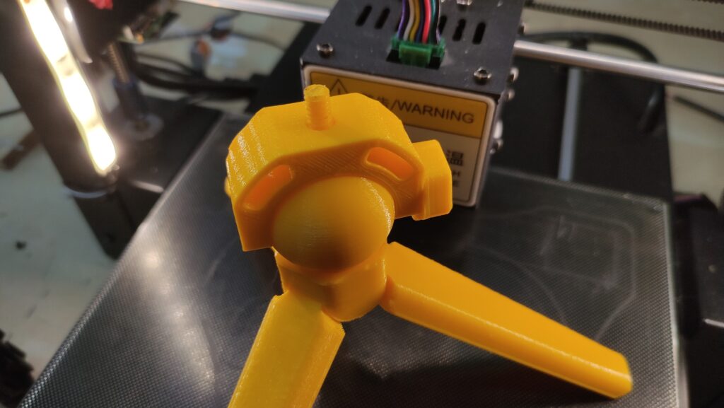
You can then screw the ball itself to the tripod and slide the other part over it:
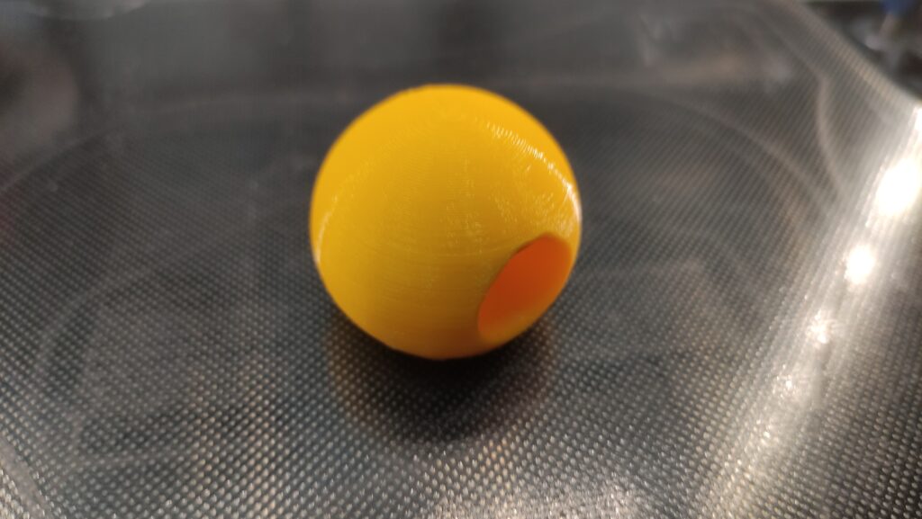
Teile für 3D Druck Stativ
3D Druck Stativ Zusammenbau

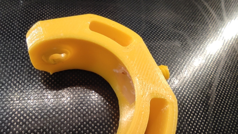
This is then fastened with an M4 screw, which I melted down a bit. Unless – like me – you don’t have an M4 screw. Then you can also drill out the hole to M5.
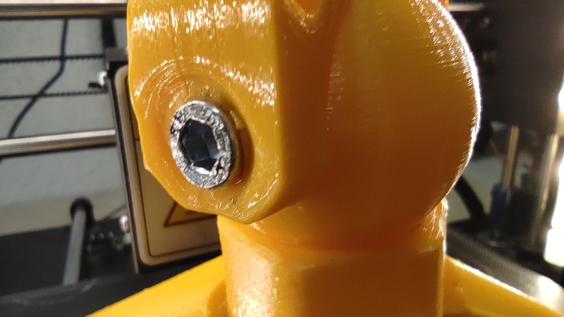
3D Druck Stativ Zusammenbau

There is a small handle with a nut so that the tripod can be moved and then fixed again.
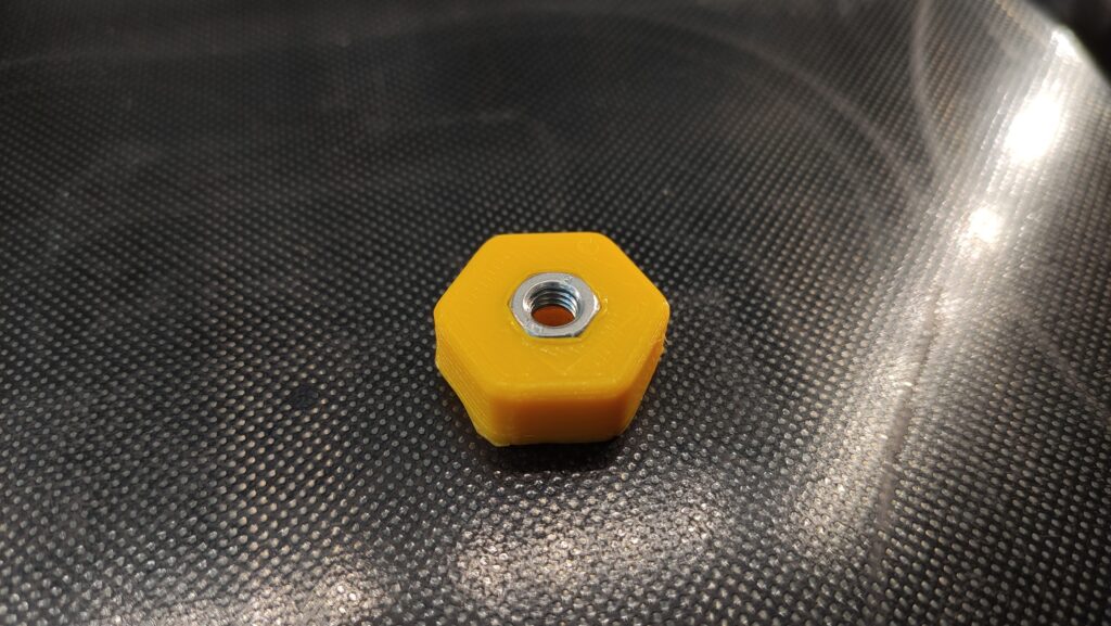
Mutter mit 3D Druck Griff
3D Druck Stativ Zusammenbau

You can now attach a camera – or the mobile phone clamp – to the screw.

Done

For me, I try to take time-lapse pictures of my 3D printer with a tripod and an old mobile phone.
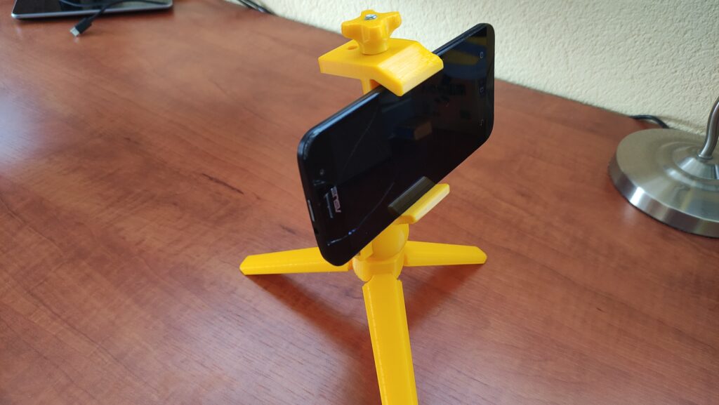
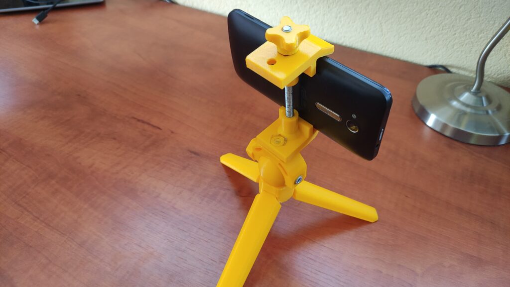
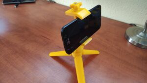
3D Druck Stativ
3D Druck Stativ

All 3D models:

Swimming pool temperature sensor with the ESP

I don’t know where I got the idea to measure the temperature in the swimming pool. But it was an interesting project.

Hardware

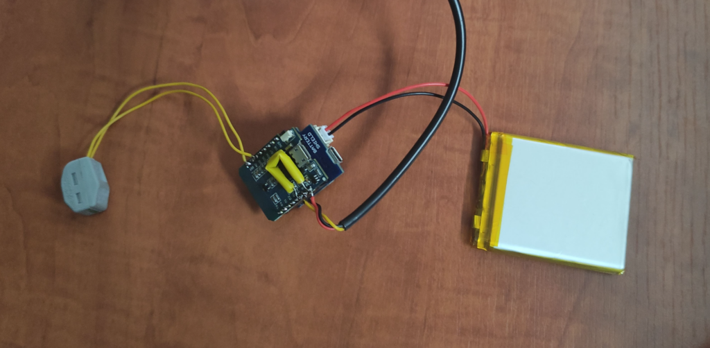
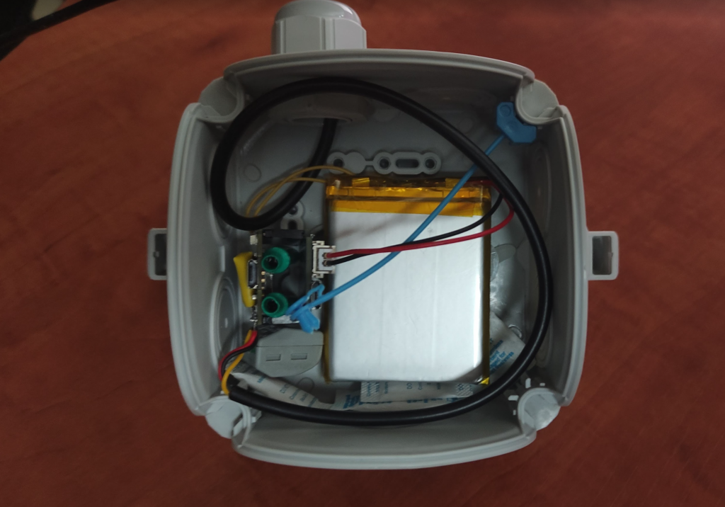
It should be battery-operated, as 230V at the pool… You know what I mean. So a Raspberry was out of the question – it needs too much power. Something smaller was needed, a microcontroller, an ESP, or more precisely a Wemos D1 mini. Plus a battery and a board to charge the battery and supply the ESP with power.

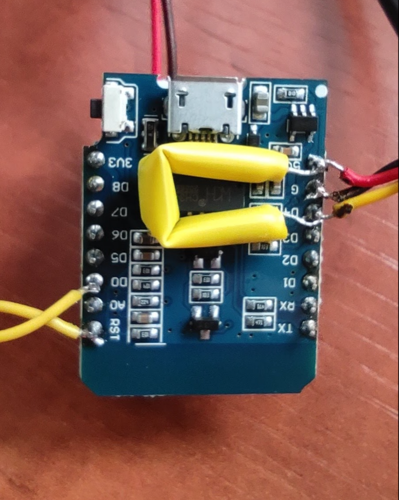
The wiring of the sensor is relatively simple – plus (red) to 5V, GND (black) to GND and the data pin (yellow) to D4. The 4.7kOhm resistor must then be connected between D4 and 5V.

For the deepSleep to work later, we have to connect D0 to RsT. However, since the connection via USB will then no longer work, it is not particularly useful to solder them directly together. I do this with 2 short cables and a clamp.

In my case, the whole thing looks like this:

Software

One thing first: my program is not pretty and there are certainly many ways to make it better, but it works. I send my values directly to the Influx database ( it would probably make more sense – especially with multiple sensors – via MQTT).

The ESP then sends the temperature every 30 minutes. The data ends up on my Homeserver, where I can then visualise it with Grafana.

Visualisation

Here is some sample data over 7 days. In green the swimming pool temperature and in yellow the outdoor temperature:

Beispieldaten Pooltemperatursensor

7″ RaspberryPi Touchscreen Wall Mount

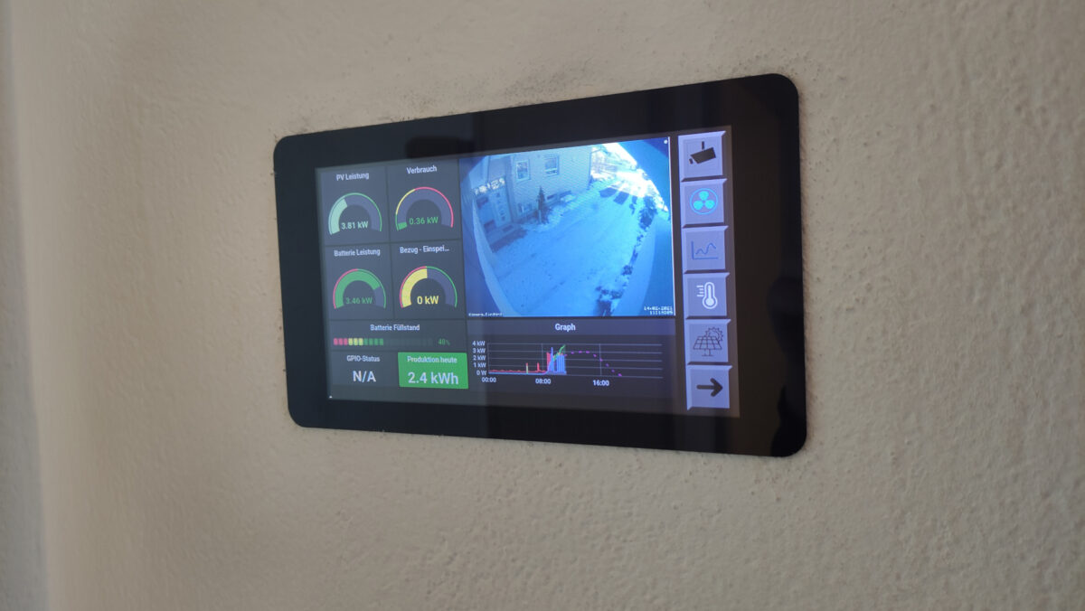
This blog entry got me thinking about installing a touchscreen like this in the wall. Here I show you how I solved this in terms of hardware and software.

(A little tip on the side: I have also already installed a 13″ display: https://blog.jjk1.de/index.php/2021/08/17/13-touchscreen-wandeinbau/)

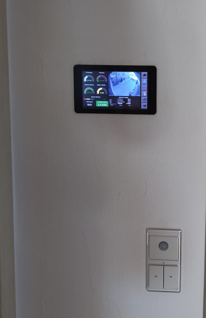
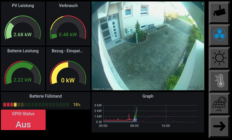
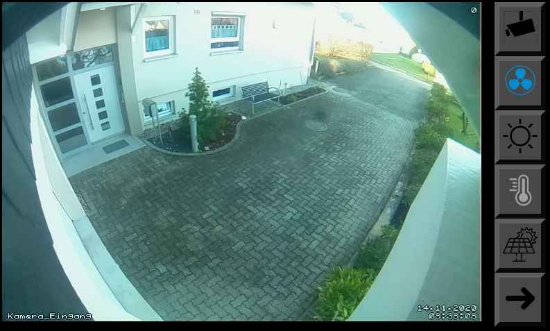
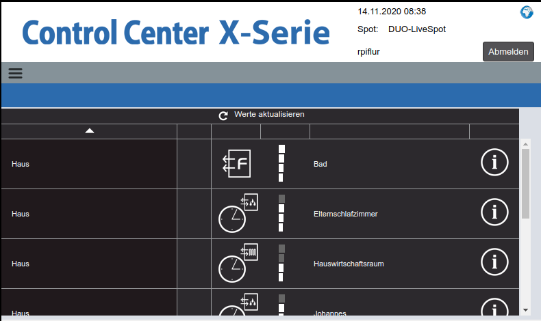
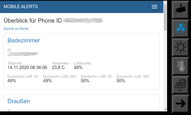
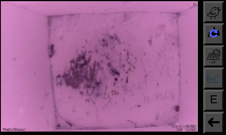
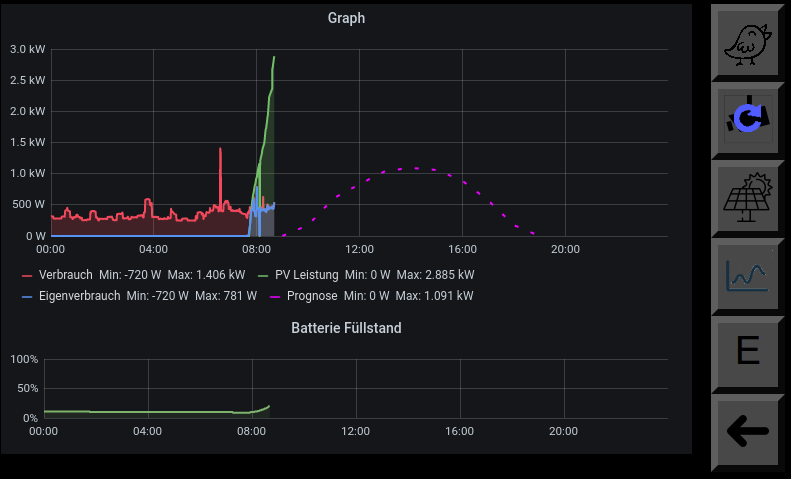
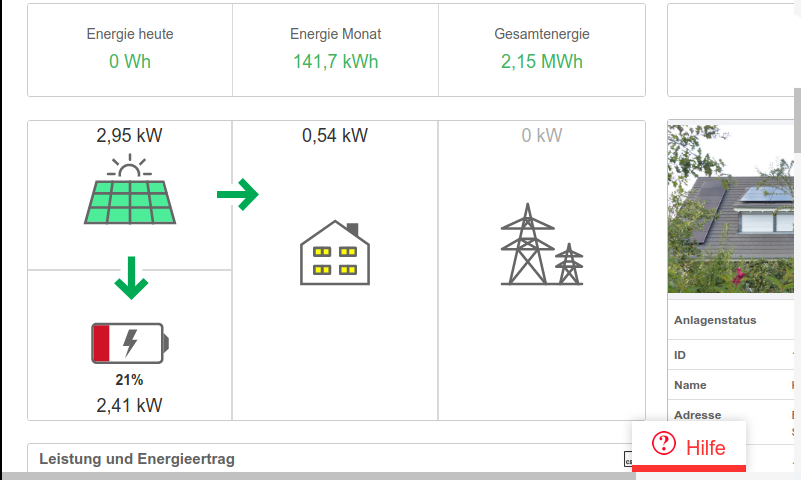
With the display, I can view the image from the surveillance camera, control the ventilation system, monitor the production of the solar system, read out My Mobile Alerts sensors and read the weather report.

Hardware

Shopping list:
Installation

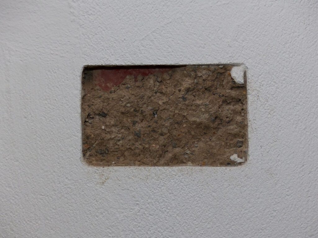
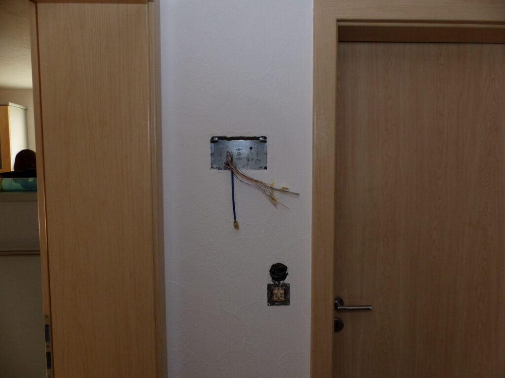
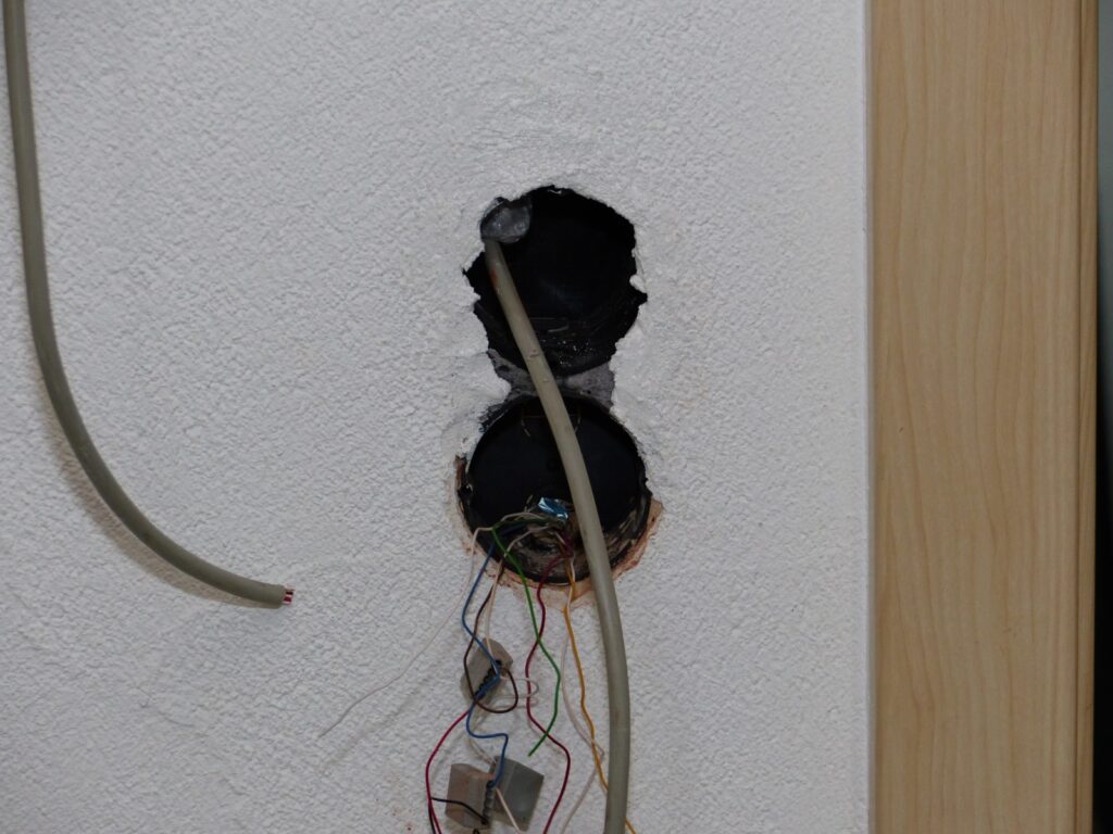
There is not much exciting to say about the installation of the enclosure. Make a hole in the wall, slide the enclosure in and fix it in place. I then installed screws in the enclosure, which are important later for mounting with the magnets.

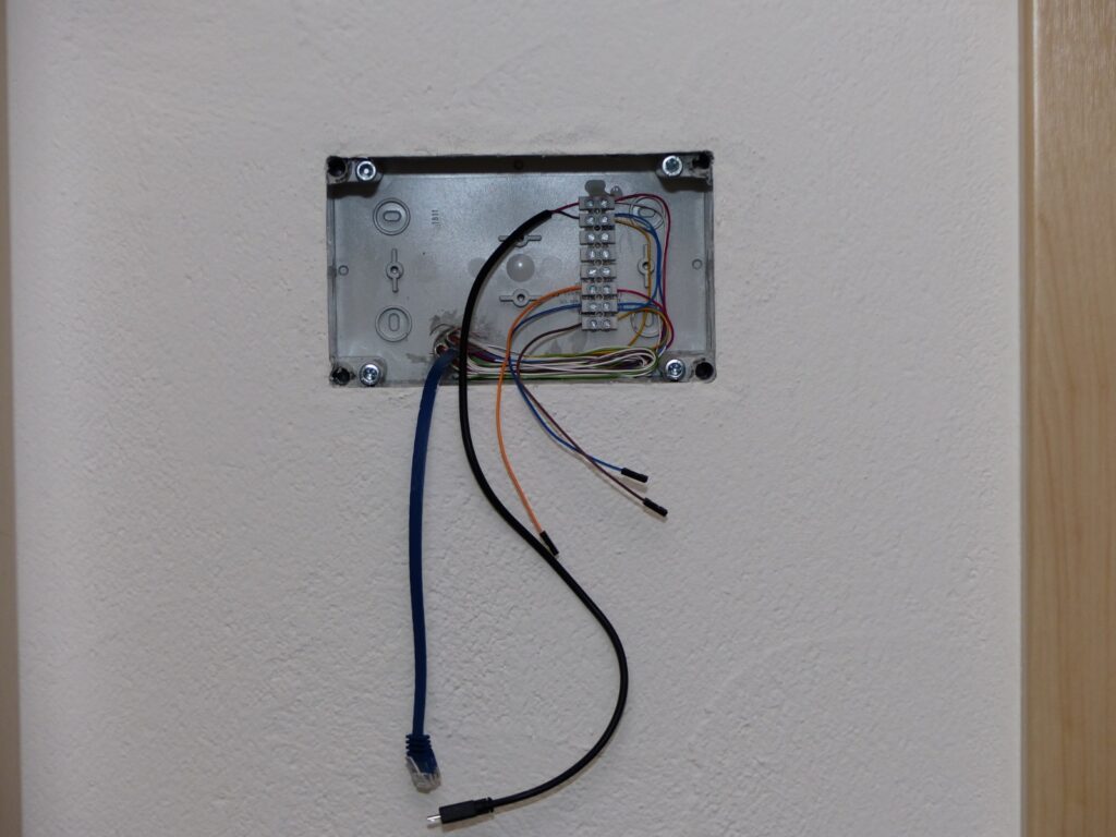
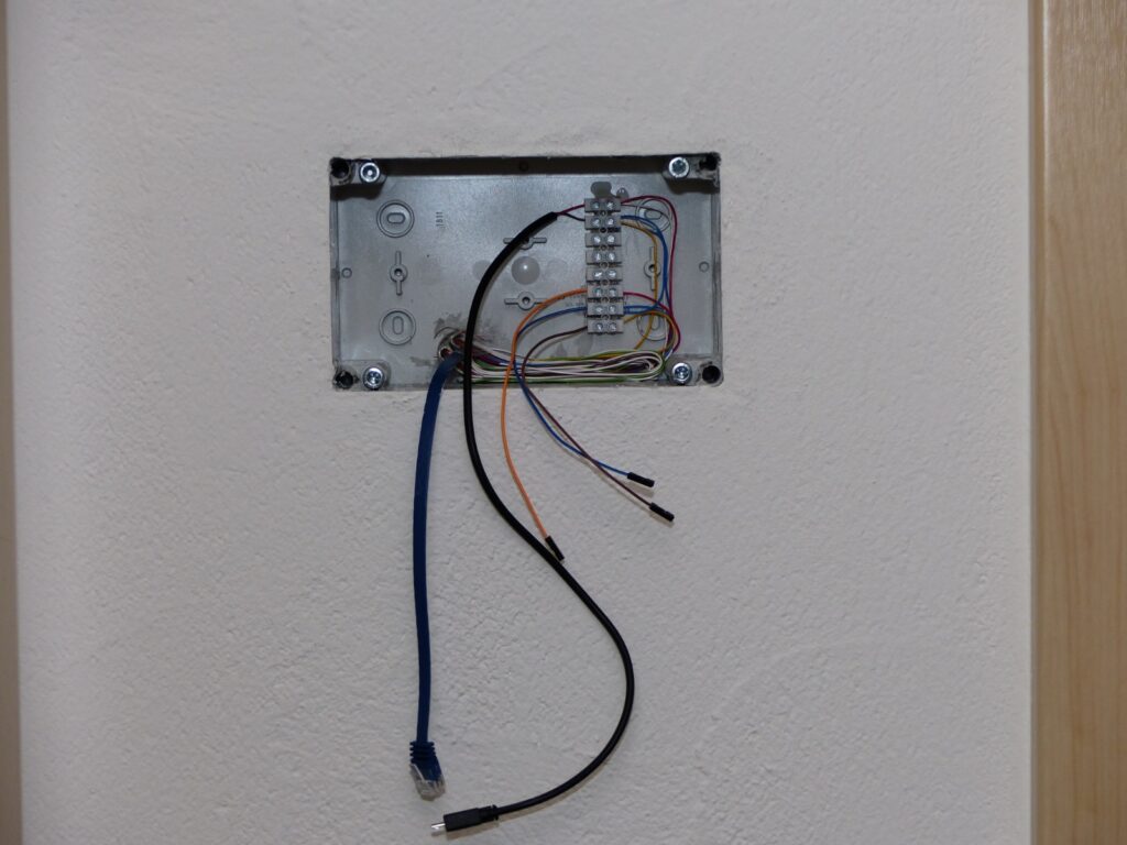
The power supply unit and a LAN socket are located in the basement directly under the display. From there, a cable goes to the power supply and a LAN cable to the top. For the cabling, I attached a luster terminal in the housing to connect the cables coming from the motion detector and the power supply with jumper cables that can later be plugged into the GPIO of the Raspberry.

To fix the display with Raspberry in the housing, you can then simply place 4 magnets on the screws, connect all cables to the Raspberry and insert the display into the housing. The magnets will hold it so that it won’t fall out by itself, but you can get it out with a little power.

I have also installed a motion sensor. This is in a blind cover under the display. It is also connected to the Raspberry at pin 10 with a cable.

Software

Script for motion sensor

I use the following Python script so that I can switch the display on and off with the motion detector:

Perhaps rights also need to be adjusted:

sudo chmod 644 /sys/class/backlight/rpi_backlight/bl_power

Graphical Interface

I use a self-written HTML page as the graphical user interface.